
Technical Artist
Dean Scott
Shot Breakdown
00:05 – 00:32 | Library Scene
Software Used: Blender, Photoshop, Nuke, Premiere Pro
Responsibilities: Modeling, Texturing, Rigging, Animation, Lighting, VFX & Physics Simulation, Rendering, Compositing
00:32 – 00:49 | Ocean Scene
Software Used: Blender, Photoshop, Nuke, Premiere Pro
Responsibilities: Modeling, Texturing, Rigging, Animation, Lighting, VFX & Physics Simulation, Rendering, Compositing
Asset Breakdown
Throughout the two shots there are several rigs that appear. In the “Library Scene,” the main character, appropriately named “The Librarian,” utilizes a combination of systems that comprise the different areas of the character. The main body rig is based on the movements of a spider. This was achieved by creating a single IK chain and duplicating it seven times, each with a roughly 30-degree rotational offset from a central pivot point. The main body acts as the cephalothorax of a spider, with the abdomen being omitted. The legs have a mirrored placement across the central axis, mimicking that of a typical tarantula. Certain joints have different rotational axes locked to achieve the desired motions. Parenting hierarchies and hooks allowed for the various greebles to respond appropriately to specific controller movements. The leg systems are then in turn controlled through a similar process to a set of layered global controls. Industrial hydraulic equipment inspired many of the modeling decisions. The neck utilizes a spine-based rig with anchor points controlling the rotational movements. These anchors are parented to the head control and body control. Pole vectors with layered influences allow for automated bending and rotating of the neck while still allowing for fine-tuned actions via user-based controls. The head itself is based on a marble bust that has since been reconstructed. The overall aesthetic is based on the steampunk subgenre “whalepunk.” A great example of this theme can be seen throughout the world of the Dishonored game franchise. Corvo Attano’s mask from said franchise provided the primary reference for the head design. All the gears in the head are controlled via a set of sliders to add rotation. A similar setup is applied to the right eye. The head also acts as an anchor point for four dual hydraulic cylinder piston systems. The animation is based on a basic spider walk cycle. Utilizing Blender’s Non-Linear Animation layering system to build on that foundation, the base animation is modified to match the required actions that take place throughout the scene. The walk follows several Bezier curves with frame durations set to match a properly moving character of this nature. The book is manipulated through the use of object parenting to the feet controls.


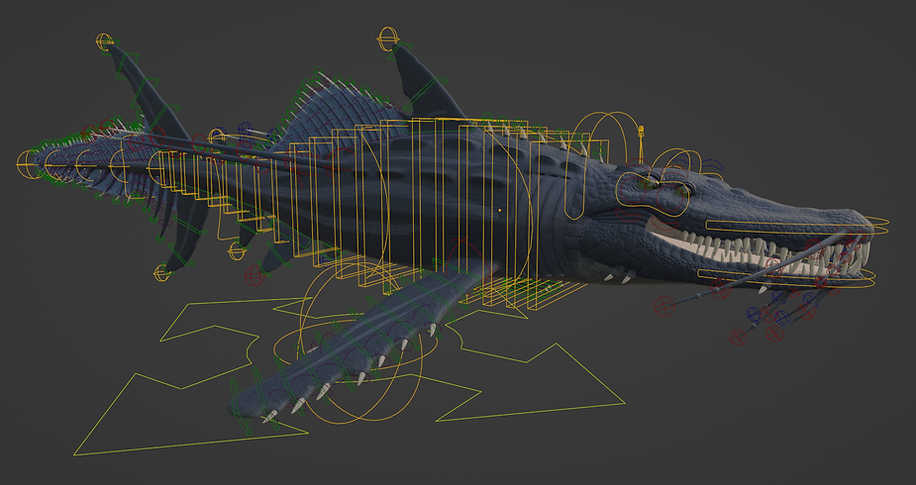
The ocean scene is comprised of an underwater creature, or “Leviathan,” and a dinghy life raft vessel. The leviathan required many separate rigging layers, while the dinghy required a combination of rigging techniques and cloth simulation systems. The Leviathan character references various aspects of whales, sharks, fish, alligators, and exotic aquatic life found in the abyssal regions of the vast oceans. The goal of this creature study was not to create a wholly original animal, but rather to understand how various anatomy systems could potentially be fused together and work in conjunction with one another. Various shark and alligator species formed the primary basis of the character. These also acted as the primary action references. Due to the theoretical nature of this creature, basic movement and swim cycles needed to be highly improvised. Through a collaboration between the Discovery Channel and the University of Miami, a live blacktip shark was captured, scanned, and animated into a community resource. This acted as a solid foundation to base the Leviathan’s movements on. The rig for this character is primarily based on an IK spline system. There are several of these in place along the body. IK chains comprise most of the secondary and tertiary systems. Various layered controls are in place for both large, sweeping actions and minute detail animating. Expressions and shared influences are heavily utilized to achieve seamless interactions between the different systems in place. Texture baking played a large part in the design process for the Leviathan. I worked on high-level detail design on a mesh consisting of approximately 24 million faces. This was in turn baked down to only 82K faces in total. I worked in reverse in terms of the typical retopology process. I created a low-poly version and created all the seams on that version. I then upscaled the poly count where needed to achieve the desired mesh density for general mesh sculpting work. I later upscaled the density again to achieve fine detail sculpting. Following this process meant that I could avoid the traditional, tedious nature of re-topologizing altogether. All I needed to do was incorporate some forward thinking into the initial topology flow of the model. Most of the Leviathan character is comprised of hand-painted textures. The sole exception being the eyes. Those were created as a reusable and fully customizable asset for any future endeavors. The hand-painted textures are, admittedly, less detailed than I would have desired. This can be attributed to several factors. Chief among these are hardware limitations and lack of access to expensive, professional software. Having said that, this could very well be an error in technique as well. I was trained in Autodesk software and needed to relearn my skills in open-source tools like Blender. Having a strong foundational knowledge base has alleviated much of the strain in regards to this process. Attempting to learn many new tools, remove the rust on my skill base, and build a new portfolio from scratch required many hours of perseverance and study.
The Dinghy is based on a traditional 12-foot-long sailing dinghy by Sparkman & Stephens. The dinghy was modeled in pieces that follow true-to-life building methods. The complex curvature of the planks and gunwales required the use of curves with profiling and mapping. Some design changes were required to translate the blueprints into a 3D environment. However, the majority of the design remains intact. All the materials are procedural. The barnacles were placed along the underside using instances and weight painting distribution techniques. This did, however, require cleanup after the fact due to the sheer number of barnacles needed. The final barnacle count neared 6,500. The sails utilized cloth physics with wind systems. The ropes were built with curves and animated with a cloth physics system that transferred simulation data from low-poly proxy meshes to high-density meshes. Various rig controls and hierarchy systems were created to produce those larger movements. While the simulation data provided the secondary and tertiary movements. The animations were later baked into .mdd mesh cache files to allow the dinghy to be easily incorporated into the ocean scene file.
The ocean scene file made use of Blender’s ocean modifier to simulate a rough ocean surface. There exist several paid Blender add-ons that can simulate water physics and interactions in a better manner. However, the goal of this project was not to show off another team’s work but my own skill. Both the scene camera and dinghy follow the ocean surface via a shrink-wrap system. Expressions and drivers create variations in the movements of these objects. Volumetric objects were utilized to create the fog as well as the underwater environment. Particle systems were used to add more detail underwater. The clouds are procedurally generated. The underwater caustics that appear on the Leviathan and in the underwater environment were imitated through the use of noise textures attached to spotlights and god rays. The leviathan follows a curve-based path and utilizes Blender’s Non-Linear Animation system to build the actions on top of a swim cycle. The scene needed to be rendered in several layers to allow proper control in the compositing process to achieve the desired visual result. Motion blur was incorporated into the render, with depth of field being integrated into the scene in the compositing process.

Throughout the duration of this project, I wrote a number of helpful scripts and tools to help speed up my workflow depending on the current objective. These tools were written with efficiency in mind. As they usually had the goal of speeding up a tedious and repetitive task. All these scripts were written in Python since they were only needed inside Blender. Unlike Maya, which usually requires code to be written in a Python wrapper such as MEL and PyMEL.
Demo Reel Breakdown
The animated book is fully rigged and follows a set of expressions for page timing as well as placement based on the rotation and location data of the front cover, spine, and back cover. The pages themselves follow a simple curve bending animation that is manipulated from said expressions. The book that gets carried to the lectern is a non-rigged prop that is later swapped with the rigged version. This was done in an effort to reduce interaction complexity between the Librarian and book rigs.
The library scene is modeled true to life in terms of both scale and construction. This realism required numerous materials and lighting setups to be built. All the materials involved are procedural and can easily be applied to objects in any scene file. Through the use of dappled lighting techniques, a highly dynamic and realistic lighting atmosphere was achieved. Motion blur is rendered for more accurate results, while depth of field was introduced to the render through a node tree in Nuke. These subtle but important details truly add to the scene’s realism.